
- Davin : +86 133 3569 6939
- Alison : +86 150 8247 5717
- Mia : +86 136 8171 1685
Skip to product information




Direct-fit OEM replacement
bolt-on installation with no welding or cutting, saving time and shop costs.
Advanced catalysis
efficiently reduces CO, HC, and NOx to meet Euro 5/6 emission limits with ease.
Premium core + coating
delivers stable high‑temperature activity and extended service life.
Efficient response
18-24 hours online, 100% response rate from human customer service within 6-8 hours.
SVIPCAT Store
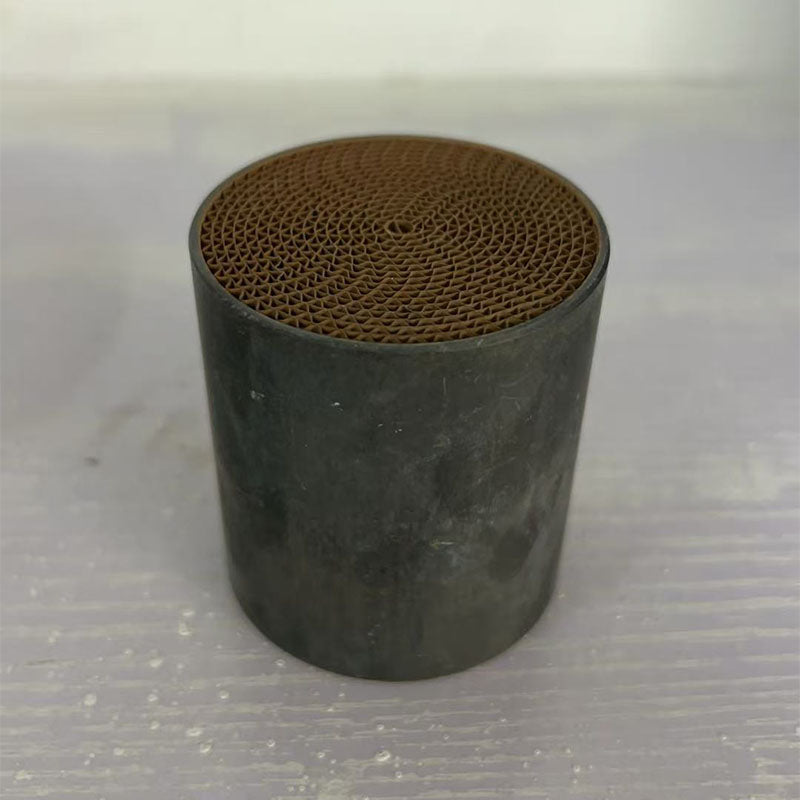
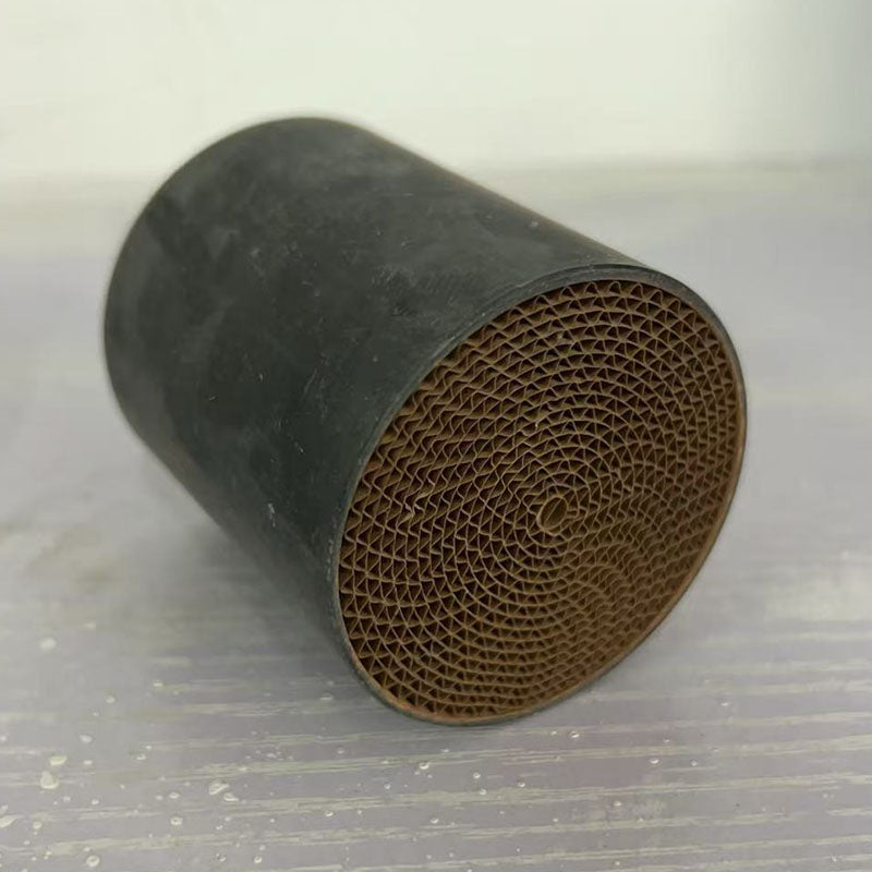
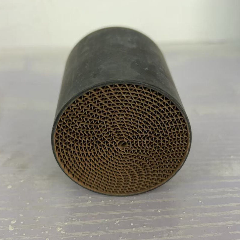
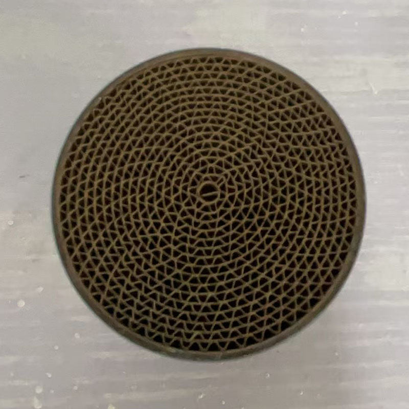
53mm Diameter Motorcycle Catalyst
Product Description
Click to expandQ1 Metal substrate material specifications
Metal honeycomb substrates are manufactured in nearly 10,000 specifications and support full non‑standard customization.
- Housing materials: 316L, 304, 444, 441 (or customer‑specified).
- Core material: FeCr21Al6 (ferritic stainless steel).
- Carrier outer diameter: 12 – 960 mm.
- Height: 9 – 150 mm.
- Cell density (CPSI): 5 – 1200 cpsi.
- Shell wall thickness: 0.5 – 3.0 mm (shell‑less option available).
- Core wall thickness: 0.03 – 0.18 mm.
- Internal core configuration: single core, S‑core, or three‑core.
- Available shapes: cylindrical, rectangular, square, racetrack (oval), elliptical, trapezoidal, pentagonal, pear‑shaped.
These substrates offer extreme design flexibility to match virtually any exhaust system requirement.
Q2 Working Principle of Catalytic Converter
A three-way catalytic converter (TWC) simultaneously converts three primary harmful exhaust pollutants into less harmful substances through oxidation and reduction reactions:
- Carbon Monoxide (CO) → oxidized into Carbon Dioxide (CO₂)
- Unburned Hydrocarbons (HC) → oxidized into Carbon Dioxide (CO₂) and Water (H₂O)
- Nitrogen Oxides (NOx) → reduced into Nitrogen (N₂) and Oxygen (O₂)
The substrate (ceramic or metal) is coated with a "washcoat" containing precious metal catalysts (platinum, palladium, rhodium). As exhaust gases pass through the honeycomb channels at high temperature (around 300°C), these metals catalyze the chemical reactions that convert approximately 98% of harmful emissions into harmless gases. This process is essential for meeting global emissions standards and protecting air quality.
Q3 Does this meet Euro 3-6 emissions standards?
Yes. Our metal and ceramic catalytic converter substrates are designed to comply with Euro 3, Euro 4, Euro 5, and Euro 6 emissions standards. When properly installed on a vehicle that is otherwise in good mechanical condition, our substrates support the vehicle's ability to meet the emissions limits for which it was originally certified. Euro 3 was introduced in 2000, with each subsequent standard imposing stricter limits — our substrates are engineered to meet the requirements across this range.
Note: Emissions compliance depends on the complete vehicle system, not just the catalytic converter. Proper engine tuning, oxygen sensor function, and overall engine health are also critical factors.
Q4 What is your warranty policy?
Our warranty policy differs by product type:
- Ceramic Muffler Cores — No warranty provided. These are mechanical components subject to wear and external factors.
- Catalytic Converter Substrates (Ceramic or Metal) — Covered by a 1‑year warranty against manufacturing defects. This warranty covers the substrate structure and catalytic coating integrity under normal use conditions.
The warranty does not cover damage caused by improper installation, engine misfire, use of leaded fuel, physical impact damage, or contamination from oil/coolant. Please retain your purchase receipt and installation records for warranty claims.
Q5 Universal metal catalytic converter installation guide
Product: Universal Metal Catalytic Converter – 400 CPSI, Total Length 250mm
This guide is specifically adapted for motorcycle catalytic converter installation. While the product is universal, the following instructions focus on motorcycle applications. Professional installation by a qualified mechanic is strongly recommended.
⚠️ Critical Installation Note – Mounting Position:
For optimal performance, the catalytic converter must be installed as close to the engine exhaust port as possible. Motorcycle exhaust gases cool rapidly over the length of the exhaust system. Placing the converter too far downstream may prevent it from reaching the required light‑off temperature (~300°C), resulting in poor emission conversion and possible check‑engine codes. Ideally, the converter should be positioned within the first 30–50 cm of the exhaust pipe after the cylinder head.
Before You Begin:
- Ensure the motorcycle is on a stable stand and the exhaust system is completely cool.
- Disconnect the battery negative terminal.
- Refer to your motorcycle's service manual for specific torque values and exhaust routing.
- Wear appropriate safety gear (gloves, eye protection).
Step 1: Remove the Existing Exhaust Components
- Remove the muffler and any intermediate pipes to access the section where the converter will be installed.
- If there is an existing converter, carefully remove it by unbolting flanges or cutting the pipe if welded.
- Clean the pipe ends thoroughly.
Step 2: Determine the Placement
- Identify the optimal location – as close to the exhaust port as possible, while still allowing clearance for suspension, swingarm, and bodywork.
- Measure the available straight pipe length. The converter's total length (250mm) must fit without excessive bending.
- Mark the cutting points on the pipe to accommodate the converter's dimensions.
Step 3: Cut and Prepare the Pipe
- Cut the exhaust pipe at the marked points using a suitable cutter or hacksaw.
- Deburr the cut ends and clean the surface with a wire brush.
- If the converter is to be welded, ensure the pipe ends are properly aligned and chamfered for welding.
Step 4: Install the Converter
- Slide the converter into the gap, ensuring the flow direction arrow points toward the exhaust outlet.
- For weld‑on installation:
- Tack‑weld the converter in place at several points.
- Check alignment and weld fully around both joints using stainless steel wire.
- Allow welds to cool gradually.
- For clamped installation:
- Use high‑quality exhaust clamps (band‑type or U‑bolt).
- Tighten clamps evenly to the recommended torque (typically 25–35 Nm).
Step 5: Reassemble and Test
- Reinstall the muffler and any other components removed.
- Reconnect the battery.
- Start the engine and check for exhaust leaks around the new joints.
- Allow the engine to reach normal operating temperature (idle for several minutes).
- Check for proper idle and acceleration response. If the check engine light appears, verify O₂ sensor connections and converter efficiency.
- Take a short test ride and re‑check all fasteners after cooling.
⚠️ Important Motorcycle‑Specific Notes:
• Heat shielding: The converter will become extremely hot. Ensure adequate clearance from fuel lines, plastic body panels, and the rider's legs. Install heat shields if necessary.
• Exhaust backpressure: Modifying the exhaust system may affect engine tuning. Some motorcycles may require a re‑map or fuel controller adjustment after installation.
• O₂ sensors: If your motorcycle uses a lambda sensor, it must be installed in the bung provided on the converter or placed in the exhaust stream before and after the converter for proper closed‑loop operation.
• Legal compliance: Check local regulations regarding catalytic converter retrofitting on motorcycles.
• Professional assistance: If you are not experienced with exhaust welding or motorcycle exhaust systems, please seek professional installation.
• Heat shielding: The converter will become extremely hot. Ensure adequate clearance from fuel lines, plastic body panels, and the rider's legs. Install heat shields if necessary.
• Exhaust backpressure: Modifying the exhaust system may affect engine tuning. Some motorcycles may require a re‑map or fuel controller adjustment after installation.
• O₂ sensors: If your motorcycle uses a lambda sensor, it must be installed in the bung provided on the converter or placed in the exhaust stream before and after the converter for proper closed‑loop operation.
• Legal compliance: Check local regulations regarding catalytic converter retrofitting on motorcycles.
• Professional assistance: If you are not experienced with exhaust welding or motorcycle exhaust systems, please seek professional installation.
Q6 Installation guide for shell-type ceramic catalytic converter
Product Reference: Original Catalytic Converter – Pt/Pd/Rh Coating
This is a complete shell-type ceramic catalytic converter (not just an internal substrate core). It comes as a fully assembled unit with the ceramic honeycomb substrate already encapsulated inside a metal shell, ready for direct bolt-on or weld-on installation. Professional installation by a qualified exhaust technician is strongly recommended. Follow these step‑by‑step guidelines:
⚠️ Before You Begin:
- Ensure the vehicle is parked on a level surface and securely supported with jack stands.
- Allow the exhaust system to cool completely before starting work — catalytic converters operate at extremely high temperatures.
- Disconnect the negative battery terminal to prevent electrical shorts and reset the ECU after installation.
- Spray all mounting bolts and flange nuts with penetrating oil a few hours ahead to ease removal.
- Refer to your vehicle's official service manual for detailed, model‑specific procedures.
- Verify compatibility: Confirm that the converter's dimensions (inlet/outlet diameter, overall length, flange orientation) match your vehicle's exhaust system.
Step 1: Locate and Access the Old Converter
- Raise the vehicle and secure it on jack stands. Allow sufficient working space under the chassis.
- Locate the existing catalytic converter in the exhaust system — typically between the exhaust manifold and the muffler.
- Remove any heat shields, underbody covers, or brackets that may obstruct access to the converter.
Step 2: Remove Oxygen Sensors (O₂ Sensors)
- Carefully disconnect the wiring harness connectors from the upstream and downstream oxygen sensors.
- Use an O₂ sensor socket or a 22mm wrench to unscrew the sensors from the old converter.
- Important: Handle the sensors with care — do not damage the sensor tips or wiring. If the sensors are seized, apply penetrating oil and allow it to soak.
- Inspect the sensors for damage or carbon buildup. Consider replacing them if they show signs of wear.
Step 3: Remove the Old Catalytic Converter
- Unbolt the flange connections at both the inlet (engine side) and outlet (exhaust side) ends of the converter.
- If the exhaust system uses a clamped connection, loosen the clamp bolts and separate the pipes.
- For weld‑on units, carefully cut the pipes at the designated points using a reciprocating saw or exhaust pipe cutter.
- Support the converter with one hand while removing the last bolts to prevent it from falling.
- Carefully lower and remove the old catalytic converter assembly from the vehicle.
Step 4: Prepare the Exhaust Pipes for Installation
- Use a wire brush or sandpaper to thoroughly clean any rust, carbon deposits, or old gasket material from the exhaust pipe flanges and mating surfaces.
- If the pipes were cut, deburr the cut edges to ensure a clean, smooth surface for welding or clamping.
- Check that the pipe ends are round and free of distortion. Use an exhaust pipe expander if needed to restore proper shape.
- Install new gaskets on both the inlet and outlet flanges — never reuse old gaskets.
Step 5: Position and Install the New Converter
- Position the new shell-type ceramic catalytic converter in place under the vehicle.
- Check flow direction: Ensure the converter is oriented correctly — look for the flow direction arrow marked on the shell. The arrow should point toward the rear of the vehicle (exhaust outlet).
- Align the inlet flange with the exhaust pipe coming from the engine, and the outlet flange with the downstream exhaust pipe.
- Confirm that all hanger brackets and mounting points align with the vehicle's existing exhaust hangers.
- Use a floor jack or transmission jack to support the converter at the correct height during fitting.
Step 6: Secure the Connections
-
For bolt‑on/flanged converters:
- Insert new bolts and nuts (use high‑temperature anti‑seize compound on the threads).
- Tighten the flange bolts evenly in a criss‑cross pattern to the manufacturer's torque specifications.
- Do not overtighten — excessive torque can warp the flanges and cause exhaust leaks.
-
For weld‑on converters:
- Tack weld the converter at multiple points (top, bottom, sides) to secure its position before final welding.
- Perform full welds around the entire circumference of both the inlet and outlet connections.
- Use appropriate welding techniques and filler material (stainless steel wire for stainless exhausts).
- Allow the welds to cool slowly to prevent warping or stress fractures.
-
For clamped connections:
- Slide the clamp over the joint and position it evenly.
- Tighten the clamp bolts to the manufacturer's torque specifications.
Step 7: Reinstall Oxygen Sensors
- Apply a small amount of anti‑seize compound to the sensor threads (avoid getting any on the sensor tip).
- Screw the upstream and downstream O₂ sensors into their respective bungs on the new converter.
- Tighten to the specified torque (typically 30–45 Nm). Do not overtighten.
- Reconnect the sensor wiring harnesses securely.
- Route the wiring away from hot exhaust components and moving parts.
Step 8: Reinstall Heat Shields and Final Checks
- Reinstall any heat shields, underbody covers, or brackets that were removed.
- Check that all hanger rods are properly seated in the rubber isolators.
- Verify that there is adequate clearance between the converter and any surrounding components (fuel lines, brake lines, wiring, body panels).
- Double‑check that all bolts, nuts, and clamps are tightened to specification.
Step 9: Reconnect Battery and Test Operation
- Reconnect the negative battery terminal.
- Start the engine and allow it to idle.
- Check for exhaust leaks: Listen for hissing sounds and feel around all connections (flanges, welds, clamps, sensor bungs) for escaping exhaust gases. Use a soapy water spray — bubbles indicate a leak.
- Allow the engine to reach normal operating temperature (the catalytic converter needs to reach light‑off temperature, typically around 300°C, to function properly).
- Verify that the check engine light remains off. If it illuminates, use an OBD‑II scanner to read the diagnostic trouble codes.
- Take a short test drive (10–15 minutes) to confirm proper function. Listen for any unusual noises or vibrations.
- After the test drive, re‑check all connections for leaks while the system is hot.
⚠️ Important Safety & Compliance Notes:
• This converter contains a ceramic substrate — handle with care. Dropping or impacting the unit can crack the ceramic core, rendering it useless.
• All welding must be performed by a qualified technician to maintain the structural integrity of the exhaust system.
• Improper installation may damage the substrate, reduce performance, void the warranty, and create safety hazards (exhaust leaks can allow carbon monoxide to enter the cabin).
• Ensure the replacement converter is the correct type for your vehicle's engine and emissions system. Using an incorrect converter can trigger check engine lights and cause failed emissions tests.
• For vehicles registered in California or other CARB‑restricted states, verify that the converter meets applicable CARB compliance requirements.
• Always follow your vehicle manufacturer's service procedures. This guide provides general instructions only — refer to your vehicle's service manual for torque specifications and model‑specific details.
• This converter contains a ceramic substrate — handle with care. Dropping or impacting the unit can crack the ceramic core, rendering it useless.
• All welding must be performed by a qualified technician to maintain the structural integrity of the exhaust system.
• Improper installation may damage the substrate, reduce performance, void the warranty, and create safety hazards (exhaust leaks can allow carbon monoxide to enter the cabin).
• Ensure the replacement converter is the correct type for your vehicle's engine and emissions system. Using an incorrect converter can trigger check engine lights and cause failed emissions tests.
• For vehicles registered in California or other CARB‑restricted states, verify that the converter meets applicable CARB compliance requirements.
• Always follow your vehicle manufacturer's service procedures. This guide provides general instructions only — refer to your vehicle's service manual for torque specifications and model‑specific details.
Q7 What are your shipping & delivery times?
Our shipping and delivery times depend on stock availability:
- If we have stock: We ship within 1–3 business days. Delivery typically takes 12–15 days (including customs clearance and duties).
- If we are out of stock: Production and handling take 15–20 business days, then delivery takes approximately 12–15 days (including customs clearance and duties).
All shipments are sent DDP (Delivered Duty Paid) – this means that all customs clearance fees, import duties, and taxes are already included in the total price you pay. You will not be charged any extra fees upon delivery.
If you need faster delivery, please contact us to arrange expedited shipping via DHL, UPS, or FEDEX (additional charges apply).
We will provide you with a tracking number as soon as your order is dispatched.
Q8 How can I contact you?
You can reach our team directly via WhatsApp or email. We are happy to assist with any questions about products, sizing, orders, or technical support.
We typically respond within 24 hours (Monday–Saturday). Please include your order number or vehicle details for faster assistance.
Q9 Where is your headquarters located?
Our company headquarters is located at:
Building C, Zhongguan Innovation Center, Dongcheng 2nd Road, Pujiang Town, Minhang District, Shanghai, China
We welcome business visits by appointment. Please contact us in advance to arrange a suitable time.
Regular price
£8.88 GBP
Taxes included.
Shipping calculated at checkout.
49 in stock
Size(diameter x height ) :
53 x 60mm
Quantity :
Whatsapp
E-mail
- Davin : KSRCAT@proton.me
- Alison:Ksrcatalytic@gmail.com
- Mia : Kesairay@proton.me
53mm Diameter Motorcycle Catalyst
Regular price
£8.88 GBP

